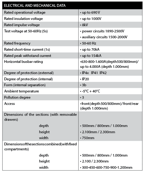
distribution and motor control switchboards with removable drawers
 The MULTISYSTEM MS-D switchboards are a brand new entry in the panorama of low voltage switchboards. They are switchboards for distribution and motor control with removable drawers featuring extreme dimensional compactness along with a high level of performance. The removable drawers make it possible to maintain the same flexibility as the switchboards with withdrawable drawers, as it is possible at any time to vary the configuration of the switchboard with the addition of drawers or to modify their positions, without cutting power to the switchboard. The optimisation of the assembly spaces inside the drawers makes it possible to limit the dimensions of the switchboard and to exploit each column to the maximum. These features help to reduce the assembly spaces in the switchboard room and lower the costs of the switchboard and the installations.
The MULTISYSTEM MS-D switchboard allows the bank
mounting of:
• combinations of motor starters
• moulded-case circuit breakers up to 250A
• miniature circuit breakers
The modular concept enables modifications to the initial configuration of the drawers even when the switchboard is powered, by simply removing and re-positioning the drawer. The compactness of the switchboard makes it possible to reduce the dimensions of a traditional switchboard with fixed compartments by 20-30%.
As an example, a column with dimensions of 750x2300x500 (LxHxD) can house up to 20 removable drawers for controlling direct start motors with power up to 15kW.
The modularity of the MS-D switchboards enables various types of installation to adapt to the configurations of the switchboard rooms.
• the columns can be positioned side by side or back to back
• the columns can be positioned against a wall
• front access to the cable connection zones
• arrival of cables can be from below (switchboards with depth 500mm) or above (switchboards with depth 500+300=800mm)
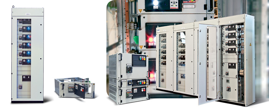
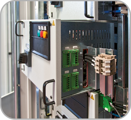
 Structure of the switchboard
Each section is made with a series of vertical and horizontal elements (uprights and side panels) in hot galvanised sheet steel. The structure is self-supporting for floor fastening. The internal parts and the removable drawers are also made of galvanised sheet steel. The front door is transparent: the frame is made of hot rolled and painted sheet steel on which a sheet of transparent polycarbonate is mounted to permit complete internal visibility of the equipment situated on the front of the drawers (lighted indicators, controls, protection and measurement instruments, etc.)
The closure panels of the sections (side and rear), as well as the front parts of the drawers, are made of hot rolled and painted sheet steel. The equipment zone constitutes the main part of a base section. The useful height is divided into modules (MS-D switchboards, height 2300mm) or 18 modules (MS-D switchboards, height 2100mm).
Each functional unit (in a removable drawer) occupies a whole number of modules (from one 1 to 5) based on the type and rated current of the equipment.In addition to the removable drawers, it is possible to assemble fixed compartments on the MS-D columns, each with its own door. In the MULTISYSTEM MS-D switchboards, the terminal block and incoming cable zones are integrated in the base column 750mm wide. On request, for cables of greater cross-section, additional cable housing columns can be coupled (300 or 450mm wide).
Main busbar compartment
The system of main busbars (horizontal) is situated in the upper part of the sections, in its own insulated zone, and is accessible from the roof. This system distributes current to the various sections that make up the electric switchboard. All the sections can receive the same horizontal busbars. The connection of the busbars of the groups of sections to be coupled is made using standardised elements.
The main horizontal busbars are made of bare copper (with surface treatments on request).
Distribution busbar compartment
The system of distribution busbars (vertical) is situated on the back of the equipment zone and is protected in a completely insulated metallic sheath. This system distributes current to the removable drawers of one section. The profile of the busbars is designed to allow the direct insertion of the pliers of the removable drawers. The busbars have a rated current of 800 A (for switchboards 500mm deep) or 1400 A (for switchboards 800mm deep).
The MULTISYSTEM MS-D switchboards are the only switchboards with removable drawers that can have the system of vertical busbars removable from the front with switchboards installed.
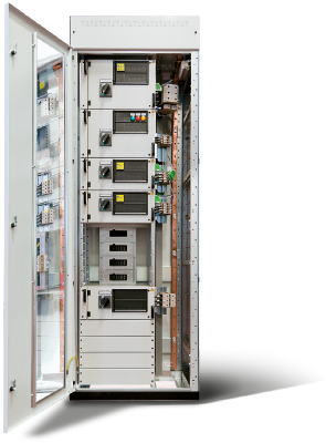
Composition of the removable drawers
The removable drawers have a mobility index of WFD (connection pliers upstream, modular terminal blocks downstream, connectors for auxiliary circuits). All the control, protection, and signalling equipment combined with the user to be powered is contained inside the drawer. So the addition of a user, even subsequently, to a switchboard in operation can be done very quickly (a few seconds) without taking the switchboard out of service. The installer only has to make the external connection of the cables.
The front width of the drawers is 450mm.
The vertical modularity of the drawers is 100 mm:
• drawer 1 module : 100mm
• drawer 2 modules : 200mm
• drawer 3 modules : 300mm
• drawer 4 modules : 400mm
• drawer 5 modules : 500mm
Each drawer is composed of:
• frame in galvanised sheet steel
• power pliers upstream (3 or 4 poles) 250 A
• mechanical protection of the incoming pliers
• support shelf in galvanised sheet steel with runner guides
• safety system that impedes drawer removal when the circuit breaker or switch-disconnector is closed, with interlock of the rotary handle on the structure of the column
• openable control and signalling panel on the front of the drawer in thermoplastic material, for installing the control, signalling, measurement or protection equipment
• external door in sheet metal, openable following the opening of the switch-off element (circuit breaker or switch-disconnector)
• internal mounting plate for the power equipment
• internal DIN rails for auxiliary equipment
• pre-drilled right wall for mounting the auxiliary connectors
• internal safety lever (fall prevention)
• two ergonomic handles for drawer movement
• Incoming pliers and automatic shutters
The power pliers incoming to the removable drawers engage on the rear busbar system by means of shutters with automatic opening and closing. They can be 3- or 4-pole with standard rated current of 250A. The connected contacts are silver-plated.
The automatic shutters comprise an insertion system that provides protection against accidental contacts (IP41), and thus insulate the vertical power busbars following removal of the drawer.
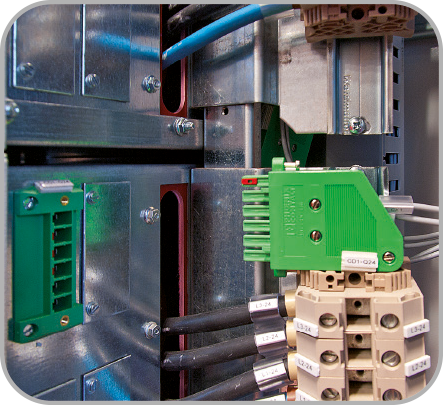
Power connections outgoing from the drawer
The drawers are equipped with a mounting plate for modular terminal blocks (integrated with the drawer). The terminal blocks are chosen according to the cross-sections of the power cables coming into the drawer. When the power cables are disconnected (e.g. to remove the drawer), the power terminal blocks are also removed with the drawer.
Auxiliary circuits outside the drawer
The removable drawers can be equipped with the following connectors for auxiliary circuits:
- drawers 1 module (height 100mm): one or two 6-pole connectors, for conductors up to 4mm2
- drawers 2,3,4,5 modules (height 200/300/400/500mm) from one to four 6-pole connectors, for conductors up to 4mm2
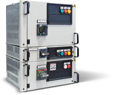
Controls, signalling,measurement or protection instruments
The front of each drawer is fitted with a control and signalling panel made of thermoplastic material (with screw fastening) to house the control and signalling equipment and any measurement or protection instruments. This panel can be opened for inspection or for making a thermographic check while the user is powered.
There are two types of panels:
type with 5 holes (pre-cut) for drawer module 1
- 1 hole 48x48mm (for measurement instruments or earth leakage relays 48x48mm)
- 4 holes for control or signalling unit Ø 22mm.
type with 10 holes (pre-cut)
- 2 holes 48x48mm (for measurement instruments or earth leakage relays 48x48mm)
- 8 holes for control or signalling unit Ø 22mm.
Manoeuvre and interlocks of the removable drawers
The manoeuvres of inserting and removing the drawers is carried out manually and do not require special tools or levers. Each drawer is equipped with mechanical interlocks to provide all the functions of operating safety. When the drawer is inserted, the mechanism of the circuit breaker of the main circuit can be locked in the open position with padlocks (up to 3 padlocks).
Procedure for removing a drawer:
- open the circuit breaker or switch-disconnector
- disconnect the power cables from the output terminal blocks (which are now unpowered)
- disconnect the auxiliary connectors
- pull the drawer up to the safety lock position (fall prevention)
-l ift the internal stop lever
The drawer can now be removed.
The estimated time for these operations is less than one minute.
Procedure for inserting a drawer:
- set the drawer on the running surface mounted on the column
- make sure that the rotary handle of the circuit breaker or switch-disconnector is in the open position
- push the drawer in; it will insert on the system of vertical busbars, located on the bottom, by means of the connection pliers upstream from the drawer
The estimated time for these operations is less than 20 seconds.
To subsequently put the drawer into operation
- connect the power cables to the output terminal blocks, keeping the circuit breaker or switch-disconnector open (rotary handle in the open position)
- connect the auxiliary connectors
- close the circuit breaker or switch-disconnector
The MULTISYSTEM MS-WP switchboards are destined to change the conception of the electric switchboard for LV power distribution. The new MULTISYSTEM MS-WP takes advantage of TQM Multisystem’s thirty years of experience in the technology of withdrawable drawers applied to power center switchboards. In fact, MULTISYSTEM MS-WP is a switchboard in which the distribution circuit breakers up to 630A are housed in withdrawable drawers with mobility index of WWW, enabling the installer to add or modify the configuration of the switchboard at any time and without taking it out of service, as would be necessary for conventional power center switchboards. Fixed compartments will be used for outgoing lines above 630A. For users up to 630A, all the control, operation, protection and signalling equipment combined with the user to be powered are contained inside the drawer. In this way, the subsequent addition of a user to a switchboard in operation can take place in an extremely limited time (just a few minutes) and without taking the switchboard out of service. The installer just has to make the external connection of the cables.