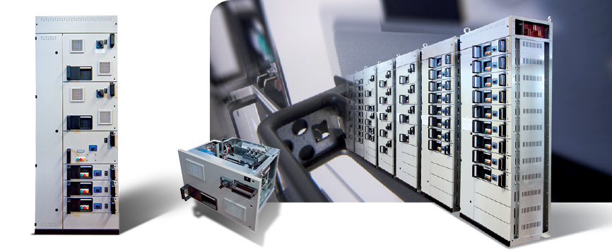
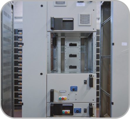
mcc switchboards with withdrawable drawers
 Structure of the switchboard
Each section is made with a series of vertical and horizontal elements (uprights and side panels) in hot galvanised sheet steel. The structure is self-supporting for floor fastening. The internal parts are also made of galvanised sheet steel. The internal partitions and the withdrawable drawers are made of hot galvanised sheet steel. The section closures (doors, cover plates) are made of hot rolled and painted sheet steel.
The equipment zone constitutes the main part of a base section. The useful height is divided into 12 modules. Each functional unit (in a withdrawable drawer) occupies a whole number of modules based on the type and rated current of the equipment.
Main busbar compartment
The system of main busbars (horizontal) is situated in the upper part of the sections, in its own zone metallically insulated, and is accessible from the roof. This system distributes current to the various sections that make up the electric switchboard. All the sections can receive the same horizontal busbars. The connection of the busbars of the groups of sections to be coupled is made using standardised elements.
Distribution busbar compartment (rear)
The system of distribution busbars (vertical) is situated on the back of the equipment zone and is protected in a completely insulated metallic sheath. This system distributes current to the withdrawable drawers of one section. The profile of the busbars is designed to allow the direct insertion of the pliers of the withdrawable drawers. The busbars are made of silvered bare copper and have a rated current of 800A.
The MULTISYSTEM MS-MCCS MSMCCH switchboards are the only switchboards with withdrawable drawers that can have the system of vertical busbars removable from the front with switchboards installed.
 Manoeuvre and interlocks of the withdrawable drawers
The manoeuvres of inserting and withdrawing the drawers are carried out manually and do not require tools or levers. Each drawer is equipped with electrical and mechanical interlocks to provide all the functions of operating safety. When the drawer is inserted, the mechanism of the circuit breaker of the main circuit can be locked in the open position with padlocks (up to 3 padlocks).
Each drawer can assume the following positions and conditions:
• Inserted position: the power circuits and auxiliary circuits are connected electrically.
• Test condition: with the drawer inserted, acting on the drawer handle, the power circuit is cut off and open while, by means of a double limit switch, the auxiliary circuit is disconnected and subsequently repowered once the power is open. In this position, the manoeuvring element of the power circuit breaker can be locked with padlocks (up to 3 padlocks).
• Cut off position in compartment: the drawer is advanced by approximately 4 cm so that both the power circuits and the auxiliary circuits are disconnected. In this position it is possible to open the front door in complete safety. Also in this position, the manoeuvring element of the power circuit breaker can be locked with padlocks (up to 3 padlocks).
• Cut off and advanced position in compartment: the drawer is advanced by another 25 cm (obviously, both the power and auxiliary circuits are disconnected). In this position it is possible to inspect the inside of the drawer while it rests on the structure of the compartment.
• Extracted position: to completely withdraw the drawer, it is necessary to release a lever inside the drawer, which is easily accessible, and pull the drawer from the switchboard. The inside lever is a fall-proof safety lock to prevent the drawer from being free to withdraw without stops on the advancement travel.
Power connections compartment (front)
The cables compartment, accessible from the front part by means of a hinged door, is positioned on the left side of each single column and houses the power cables and auxiliary cables, which are joined respectively to the power connections (protected by a removable transparent cap) and to the auxiliary terminal blocks combined with the withdrawable drawers for the entire height of the column.
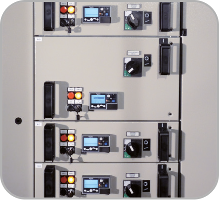
Withdrawable drawers
Each drawer is a completely withdrawable unit, complete with power and auxiliary pliers, upstream and downstream, that contains the electrical components necessary for the control of the user. The withdrawable drawers are modular. They are available in 4 modules: • 1/12 • 2/12 • 3/12 • 4/12. In a column all the combinations of drawers can be fitted up to 12/12. The modular concept allows modifications with respect to the initial configuration of the drawers even with the switchboard under live voltage, with the simple extraction and repositioning of the drawer. Automatic shutters insulate the power busbars upstream following the extraction of the moving part. The shutters are composed of a system of special insertion openings that create the protection against accidental contacts (IP41). All the withdrawable drawers have a “test” condition. In this condition, the power circuits are open upstream. It is therefore possible to check the operation of the auxiliary circuits.
The incoming pliers of the withdrawable drawers
The incoming pliers of the withdrawable drawers are engaged on the rear busbar system by means of shutters with automatic opening and closing. They can be 3- or 4-pole with standard rated current of 250A. The pliers can be fitted in parallel in the drawers in order to have rated currents up to 400A.
The outgoing pliers of the withdrawable drawers
The outgoing pliers can be 3- or 4-pole with rated current of 125A or 400A. Each outgoing plier has a large number of auxiliary terminals (26 for size 1 drawers and up to 52 for drawers of sizes 2, 3 and 4).