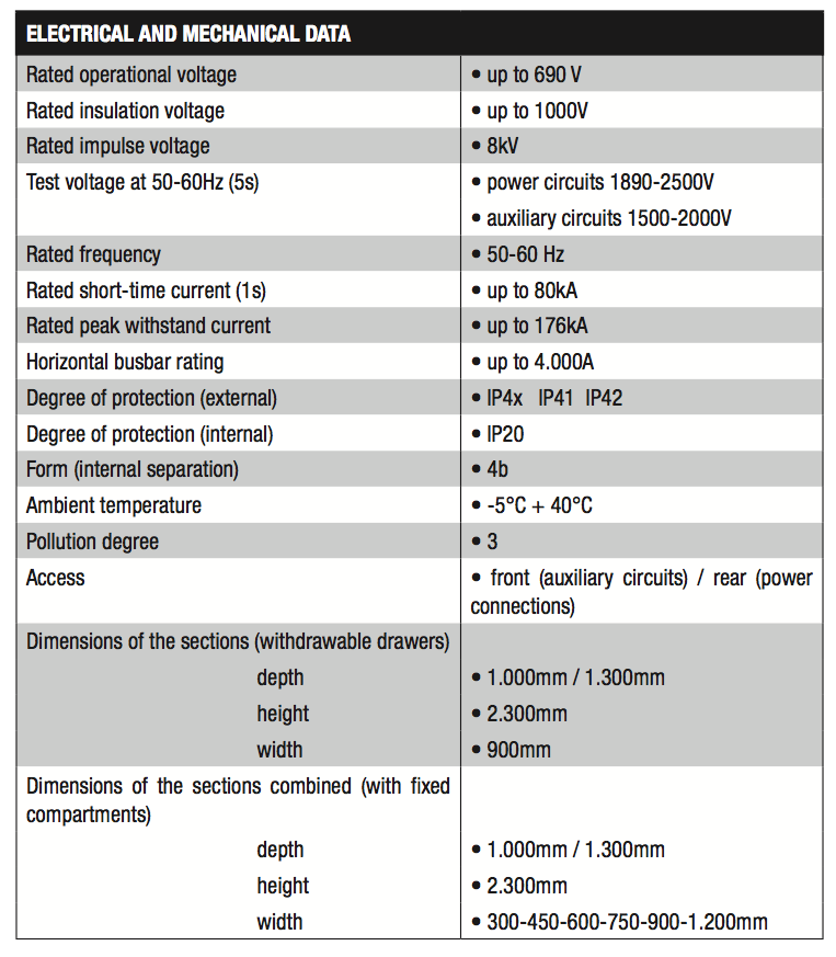
POWER CENTER SWITCHBOARDS WITH WITHDRAWABLE DRAWERS
 The MULTISYSTEM MS-WP switchboards are destined to change the conception of the electric switchboard for LV power distribution. The new MULTISYSTEM MS-WP takes advantage of TQM Multisystem’s thirty years of experience in the technology of withdrawable drawers applied to power center switchboards. In fact, MULTISYSTEM MS-WP is a switchboard in which the distribution circuit breakers up to 630A are housed in withdrawable drawers with mobility index of WWW, enabling the installer to add or modify the configuration of the switchboard at any time and without taking it out of service, as would be necessary for conventional power center switchboards. Fixed compartments will be used for outgoing lines above 630A. For users up to 630A, all the control, operation, protection and signalling equipment combined with the user to be powered are contained inside the drawer. In this way, the subsequent addition of a user to a switchboard in operation can take place in an extremely limited time (just a few minutes) and without taking the switchboard out of service. The installer just has to make the external connection of the cables.
In the withdrawable drawers, the incoming pliers (250A or 630A) and the outgoing pliers (from 250A up to 630A) are always generously sized with respect to the rated currents they have to withstand. The withdrawable drawers include the test position as standard: in this way, even for motorised circuit breakers, the functionality of the circuit breaker and of the auxiliary equipment combined with it can be checked. On the front of each drawer there is a plastic door where the control and signalling equipment is positioned, along with any measurement or protection instruments: this door can be opened with the user in operation for inspection purposes or for a thermographic check. The arrangement of the withdrawable drawers on the columns of the MULTISYSTEM MS-WP switchboards can be varied at any time without cutting power to the switchboard. The MULTISYSTEM switchboard allows mounting of: – combinations of motor starters – moulded-case circuit breakers up to 630A The modular concept enables modifications of the initial configuration of the drawers even when the switchboard is powered, by simply removing the drawer and re-positioning it. – access to the connection zones of the power cables is from the back – access to the connection zones of the auxiliary cables from the back or the front – arrival of cables can be from below (switchboards with depth 1000mm) or above (switchboards with depth 1300). The MS-WP switchboards can be combined with any other type from the MULTISYSTEM line (e.g. there can be MS-WP columns combined with MS-D, MS-MCCS, MS-MCCH columns, etc.).
Structure of the switchboard
Each section is made with a series of vertical and horizontal elements (uprights and side panels) in hot galvanised sheet steel. The structure is self-supporting for floor fastening. The internal parts are also made of galvanised sheet steel. The closure panels of the sections (side and rear), as well as the front parts of the drawers, are made of hot rolled and painted sheet steel. The base section contains the power equipment and the busbar systems (main system, distribution system, and protection conductors PE). The base section is subdivided into 4 zones separated by diaphragms in metal or in insulating material: – main busbar zone – distribution busbar zone – equipment zone (withdrawable drawers or fixed cells) – auxiliary zone The minimum form of separation of the MULTISYSTEM MS-WP switchboard is 3b. The internal degree of protection IP2X is ensured with the drawers in all the positions (test, disconnected, extracted). The equipment zone forms the main part of a base section. The useful height is divided into 18 modules of 100mm each. The withdrawable drawers are proposed in two sizes: – drawer module 2 (height 200mm): is used for line start up to 250 A – drawer module 3 (height 300mm): is used for line start up to 630 A
For the creation of withdrawable drawers for motor start, the same drawers are used (module 2 or module 3) depending on the equipment installed inside. In addition to the withdrawable drawers, on the MS-WP columns it is possible to fit fixed cells, each with its own door.
Main distribution busbar compartment
The system of main busbars (horizontal) is situated in the upper part of the sections, in its own zone metallically insulated, and is accessible from the roof and from the back. This system distributes current to the various sections that make up the electric switchboard. All the sections can receive the same horizontal busbars.The busbars have a rated current up to 4.000 A.The connection of the busbars of the groups of sections to be coupled is made using standardised elements.The main horizontal busbars are made of bare copper (with surface treatments on request).
Secondary distribution busbar compartment
The secondary system of distribution busbars (vertical) is situated on the back of the equipment zone and is protected in a completely insulated metallic sheath. This system distributes the current to the withdrawable drawers or to the fixed cells of one section. The rear separation of the busbars is made with modular metal diaphragms with air vents. The profile of the busbars is designed to enable direct insertion of the pliers of the withdrawable drawers. The busbars have a rated current of 2100 A or 1250 A (other rated currents on request). The vertical busbars are, as standard, in silver-plated copper.
Composition of the withdrawable drawers
The withdrawable drawers have a mobility index of WWW. All the control, protection, and signalling equipment combined with the user to be powered are contained in the drawer. So the addition of a user, even subsequently, to a switchboard in operation can be done very quickly (a few seconds) without taking the switchboard out of service. The installer only has to make the external connection of the cables.
The vertical modularity of the drawers is 100 mm:
- drawer 2 modules : 200mm
- drawer 3 modules : 300mm
Each drawer is composed of:
- frame in galvanised sheet steel
- power pliers upstream (3 or 4 poles) with standard rated currents of 250A, 400A, 630A.
- power pliers downstream (3 o 4 poles) with standard rated currents of 250A, 630A.
- lateral auxiliary pliers with 26 auxiliary terminals
- mechanical protection of the incoming pliers
- support shelf in galvanised sheet steel with runner guides
- safety system that impedes drawer removal when the circuit breaker or switch-disconnector is closed, with interlock of the rotary handle on the structure of the column
- openable panel on the front of the drawer in thermoplastic material, for installing the control, signalling, measurement, or protection equipment
- internal mounting plate for the power equipment
- internal DIN rails for auxiliary equipment
- internal safety lever (fall prevention)
- two ergonomic handles for drawer movement
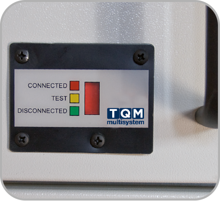
- mechanical indication of the position of the drawer on the front (connected, test, disconnected)
- red mechanical pushbutton for the consent for drawer movement
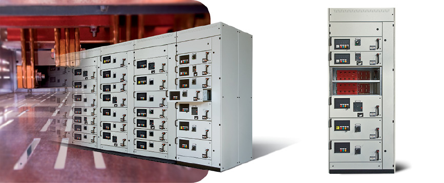
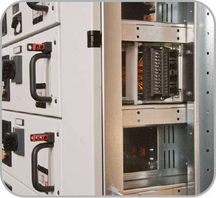
Incoming pliers
The power pliers upstream from the withdrawable drawers engage on the rear busbar system by means of grills for protecting the busbars that are red in colour and have IP2X degree of protection. The pliers can be 3- or 4-pole with standard rated currents of 250A, 400A, 630A. The connected contacts are silver-plated.
Outgoing pliers
The power pliers downstream from the withdrawable drawers engage on shaped elements in bare copper which, in turn, receive the power cables incoming to the switchboard in the part that protrudes in the rear cable zone. The pliers can be 3- or 4-pole with standard rated currents of 250A and 630A. The connected contacts are silver-plated.
Auxiliary pliers
Each auxiliary pliers has 26 terminals and is mounted on a support system that makes it possible to have:
- with drawer in the connected position (power pliers upstream and downstream connected): auxiliary pliers connected
- with drawer in test position: the power pliers (upstream and downstream) are disconnected, while the auxiliary pliers remain connected; in this way, the auxiliary circuits are active and the operation of the drawer can be tested with the power disactivated.
- with drawer in disconnected position (power pliers upstream and downstream disconnected): auxiliary pliers disconnected
Note: In the disconnected position, the drawer is still mounted on the switchboard, advanced by a few centimetres with respect to the test position, but is completely disactivated. From this position it is possible to proceed to the complete withdrawal of the drawer using the internal safety lever (fall prevention).
Controls, signalling, measurement or protection instruments
The front of each drawer is fitted with a control and signalling panel made of thermoplastic material (with screw fastening) to house the control and signalling equipment and any measurement or protection instruments. This panel can be opened for inspection or for making a thermographic check while the user is powered.
These panels are provided with:
- 10 holes (pre-cut):
- 2 holes 48x48mm (for measurement instruments or earth leakage relays 48x48mm)
- 8 holes for control or signalling unit Ø 22mm.
Manoeuvre and interlocks of the withdrawable drawers
The drawer manoeuvres are carried out manually and do not require special tools or levers. Each drawer is equipped with mechanical interlocks to provide all the functions of operating safety.
When the drawer is inserted, the mechanism of the circuit breaker of the main circuit can be locked in the open position with padlocks (up to 3 padlocks). The mechanical pushbutton for the consent for drawer movement can also be locked with padlocks (up to 3 padlocks). With the drawer completely removed, the degree of protection is IP2X.
Drawer movement
(for circuit breakers with extended rotary handle)
Procedure for inserting a drawer:
- set the drawer on the running surface mounted on the column
- make sure that the rotary handle of the circuit breaker or switch-disconnector is in the open position
- press and hold the red mechanical pushbutton for the consent for movement
- push the drawer all the way in: the upstream power connection pliers will insert on the vertical busbar system, the downstream power connection pliers will insert on shaped elements in copper for connection to the external cables, the moving part of the auxiliary pliers will insert on its fixed part.
- the mechanical position signal will go to RED (CONNECTED)
The estimated time for these operations is less than 20 seconds.
Procedure for withdrawing a drawer:
a) from the connected position to the test position
- open the circuit breaker or switch-disconnector (with the extended rotary handle)
- press and hold the red mechanical pushbutton for the consent for movement
- pull the drawer out until it reaches the test position
- the mechanical position signal will go to YELLOW (TEST)
- release the red mechanical pushbutton for the consent for movement
b) from the test position to the disconnected position
- press and hold the red mechanical pushbutton for the consent for movement
- pull the drawer out until it reaches the disconnected position
- the mechanical position signal will go to GREEN (DISCONNECTED)
- release the red mechanical pushbutton for the consent for movement
c) removing the drawer
- press and hold the red mechanical pushbutton for the consent for movement
- pull the drawer out until it is stopped by the safety locking mechanism (fall prevention)
- release the red mechanical pushbutton for the consent for movement
- lift the internal lever of the fall prevention mechanism
- the drawer can now be removed
The estimated time for a complete removal of the drawer, from the connected position to the removal, is less than 10 seconds.
Moving the drawers
(for circuit-breakers with motor mechanism)
The circuit-breakers with motor mechanism cannot fit an extended rotary handle. In order to insert or withdraw a drawer with the guarantee that the circuit-breaker is open, TQM Multisystem has created an opening mechanism that acts on the original manufacturer circuit-breaker safety trip interlocks. A dedicated lever situated on the front of the drawer, under the front panel of the circuit-breaker motor mechanism, activates the original safety trip interlock, which in turn automatically opens the circuit-breaker or, in the opposite position, allows its closure.
This mechanism, in turn, is interlocked with the red mechanical pushbutton for the consent for movement of the drawer.
The operations of drawer insertion or withdrawal are similar to those for the circuit-breakers with extended rotary handle, with the only difference that, instead of operating on the extended rotary handle of the circuit-breaker, it works with the lever of the opening mechanism of the circuit-breaker with motor mechanism described above.